
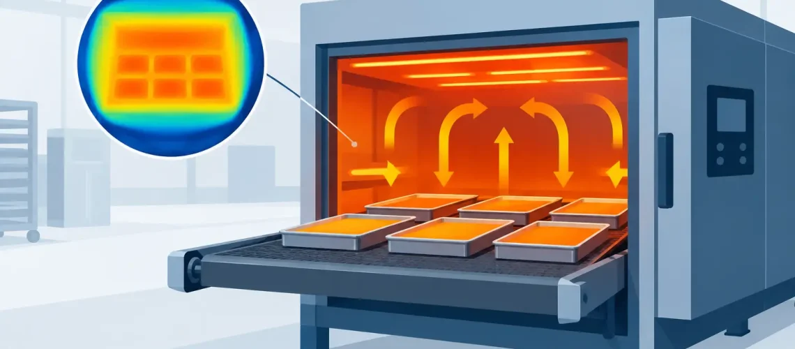
A batch can look finished and still be a process failure. One area of a loaded oven may fully cure a coating while another remains under-cured. A dryer may remove moisture from outer surfaces while leaving dense products damp at the center. In sanitation work, a cold area can compromise the intended exposure of every item placed there. This thermal uniformity guide explains how to evaluate and manage temperature consistency in industrial ovens, furnaces, dryers, and sterilization equipment.
For plant teams, thermal uniformity is not a laboratory exercise. It is the practical difference between repeatable output and costly variation. It influences product quality, energy use, cycle time, traceability, maintenance planning, and confidence in the equipment used across every shift.
What thermal uniformity means in production
Thermal uniformity describes how closely the temperature throughout a defined working zone stays within a specified range during a defined period. If an oven is set to 350°F and the approved tolerance is plus or minus 10°F, the usable workspace must remain between 340°F and 360°F when tested under the agreed conditions.
The key phrase is defined working zone. The chamber wall, door surface, and space directly beside heating elements are not always suitable locations for production parts. A useful working zone is the volume where product, racks, trays, or fixtures can reliably receive the required heat.
Uniformity is also different from controller accuracy. A controller can accurately display 350°F at its sensing point while another point in the chamber runs much cooler. Calibration confirms whether an instrument measures correctly. Uniformity confirms whether the process environment is consistent across the load area. Both are necessary, but neither replaces the other.
Why temperature variation creates real operating risk
Heat moves through equipment and products in different ways. Air circulation, radiation from heaters, conduction through racks, exhaust flow, door leakage, insulation condition, and product mass all affect the result. Even a well-built chamber will have thermal patterns. The engineering task is to identify those patterns, keep them within the required tolerance, and design the process around them.
For powder coating, paint curing, adhesive bonding, and composite processing, uneven temperature can cause poor adhesion, uneven finish, weak bonds, discoloration, or premature field failures. In food-related drying and sanitation processes, variation may affect moisture targets, shelf life, cleaning effectiveness, or throughput. In healthcare, laundry, and hygiene applications, the concern is whether every item receives the required time-at-temperature exposure.
The impact may not appear immediately. A coating may pass visual inspection but fail later under abrasion or corrosion. A dried component may seem acceptable until trapped moisture causes damage during storage or assembly. That is why a stable setpoint alone is not sufficient evidence of process control.
Thermal Uniformity Guide: Start with the process requirement
Before specifying a tolerance, define what the product actually needs. The answer depends on the application, material, load configuration, and quality requirement. A light aluminum part, a heavy steel fixture, and a densely packed trolley do not heat at the same rate, even in the same chamber.
Start by documenting the required product temperature, acceptable temperature range, required soak duration, maximum cycle time, and expected load size. Also define whether the process requirement applies to air temperature, product temperature, or both. Many curing and sanitation processes are governed by the temperature reached by the product itself, not merely the chamber air.
This distinction is especially important when thermal mass is high. The air may reach setpoint quickly while the product core remains below target. A reliable cycle may therefore need a heat-up stage followed by a verified soak period. For critical applications, representative load sensors or product probes can provide stronger evidence than chamber readings alone.
The allowable tolerance should be based on product need, not a generic preference. Tighter uniformity can require more sophisticated airflow design, zoning, controls, sensor placement, and commissioning time. It can also increase capital cost and energy demand. Where the product allows a wider range, an appropriately designed system may provide better lifecycle value without compromising quality.
How a thermal uniformity survey works
A thermal uniformity survey, often called a TUS, measures temperature at multiple locations throughout the working zone. The survey is performed using calibrated data loggers or thermocouples placed at selected points, then recorded over the required cycle period.
A meaningful survey begins with a documented test plan. It should identify the chamber setpoint, operating temperature, empty or loaded condition, sensor locations, logging interval, stabilization criteria, test duration, and acceptance tolerance. Without these details, results may be difficult to compare over time or defend during a customer audit.
Sensor placement matters. Points should represent the corners, center, upper and lower areas, and locations likely to experience weaker airflow or higher heat exposure. Large equipment may require a grid across the entire usable volume. Where racks, trolleys, or baskets are used, the survey should reflect how production is actually loaded.
An empty-chamber test is useful for understanding the equipment itself. A loaded test is usually more representative of production reality. Loads can obstruct airflow, absorb heat, and create cold zones between closely packed items. For this reason, an oven that passes an empty survey may still need adjustment for a dense production load.
The test should not end as soon as the display reaches setpoint. Temperature data must be reviewed after the chamber has stabilized and through the defined soak period. The results show the highest and lowest readings at each monitored point, the spread across the zone, and whether every point remained inside the approved range.
Equipment features that support better uniformity
Uniformity begins with mechanical and thermal design. Recirculating airflow is often central to performance because it moves heat through the working zone rather than allowing it to collect near heaters or at the top of a chamber. Fan capacity, duct design, baffles, and return-air paths must be matched to the chamber size and intended load.
Airflow should be strong enough to reduce temperature differences, but not so aggressive that it disturbs lightweight materials, damages sensitive surfaces, or creates uneven drying patterns. Direction matters as well. Horizontal, vertical, or reversible airflow may be selected based on the product geometry and rack arrangement.
Heating capacity must match the process demand. An undersized system may recover slowly after loading or door opening, while an oversized system with poorly tuned controls can overshoot. Multiple heating zones can improve control in long ovens, large chambers, or applications with known heat-loss differences near doors and exhaust sections.
Insulation and sealing deserve equal attention. Damaged door gaskets, warped doors, uninsulated penetrations, and leaks around service openings can create local cold areas while increasing energy consumption. Exhaust systems also need careful balancing. Too much exhaust can pull heated air from the chamber faster than the recirculation system can compensate.
Common causes of failed uniformity tests
When a survey fails, the solution is not always a higher setpoint. Raising the setpoint can hide a cold point while overheating another area. The goal is to correct the source of variation.
Common causes include blocked ducts, contaminated fan blades, worn fan motors, failed heaters, incorrect airflow direction, poor baffle position, leaking doors, and inaccurate sensors. Production changes can also be responsible. A new fixture, a taller rack, different packaging, or a denser load pattern can alter airflow enough to affect results.
Maintenance teams should inspect these fundamentals before making major changes to control settings. In many cases, cleaning circulation components, replacing a gasket, correcting a fan rotation issue, or restoring damaged insulation can materially improve chamber performance.
Maintaining uniformity between surveys
A passing survey is a point-in-time result, not a permanent guarantee. Establish a preventive maintenance plan that includes fan and motor inspection, heater checks, door-seal inspection, airflow-path cleaning, control verification, and calibration review. The appropriate frequency depends on operating hours, process criticality, load contamination, and the consequences of a failed cycle.
Operators also need clear loading instructions. Define rack spacing, maximum load height, product orientation, allowable weight, and areas that must remain clear for airflow. If a process is validated with one loading pattern but run daily with another, the original test may no longer represent actual conditions.
Trend operating data where practical. Longer heat-up times, increased energy consumption, frequent controller corrections, or repeated quality variation can signal declining performance before a formal survey fails. Early action protects production schedules and reduces unplanned service work.
For custom thermal equipment, the strongest results come from treating uniformity as a joint design and operating responsibility. REK Engineering Machinery works with facility teams to align chamber dimensions, airflow, controls, loading practices, and service requirements with the actual process, rather than forcing a critical application into a generic configuration.
The most useful question is not simply whether an oven reaches temperature. Ask whether every product, in every approved load position, receives the controlled heat exposure the process requires. That question leads to better specifications, more meaningful testing, and equipment performance that remains dependable long after installation.